Atrophy's Heated Grips
History
When I bought my Trophy, I was too mean to have any accessories. Having ridden many miles in all weathers (except if there's ice on the road. I am too much of a wimp to ride then), I decided I needed heated handlebar grips. Since I am still mean, I wasn't about to shell out £120-odd, or even after-market ones at around £50.
Caveat
This is supposed to be a statement that absolves me from any responsibility for anything you do to your bike or yourself. Not being of a legal persuasion I don't know the proper words, so if you or your next of kin plan on suing me if anything goes wrong, or not as you'd hoped, please go away and don't even read any further.
Design Considerations
I didn't want to do anything that couldn't be reversed, so that if I did want to sell my bike, I could easily revert it to manufacturer's specification.So it had to leave the original grips in place, and no drilling for switches or whatever.
I wanted some heat adjustment. Although a wide range of heat levels would be nice, I also wanted to keep it simple (less to go wrong), so I decided on two heat levels, hot and warm.
Design
The design can be viewed from two angles, the electrical and the mechanical. The electrical design enables an easy understanding of how it works, the mechanical is the physical embodiment.
Electrical Circuit Design
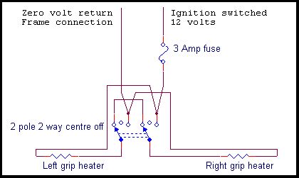
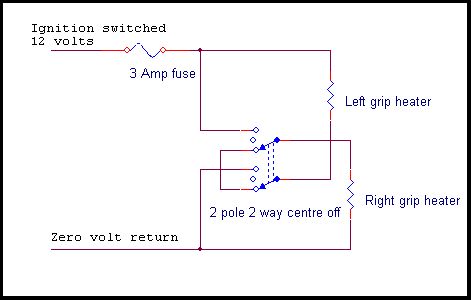 The way this works is to have the two grip heaters in parallel across the battery for full heat, or in series for low heat (actually a quarter of the full). This way, no extra components are required.
The disadvantage of this simplicity is that there is a wide gap between the two heat settings; the grips are either very hot or only warm. Still, they do work.
From reading everything I could lay my hands on, it seemed that a good maximum heat would be about 25 watts shared between the two grips for full power. From this the required resistance of the grips can be calculated from the formula:
| W = V² ÷ R |
The voltage of a battery being properly charged is about 14 volts, so we can put some figures into our equation:
| 25 = 14² ÷ R |
| R = 14² ÷ 25 |
Mechanical Design
The way I decided to make these heaters was by using some resistance wire spirally wound round the grip, held in place with some shrink-wrap sleeving. So, stuff required:- Switch, 2 pole, 2 way, centre off, sealed against the weather (this is on a motorcycle)
- Resistance wire (see later for details)
- Connecting wire - capable of carrying 5 amps, with tough enough insulation for use on the bike
- Heatshrink - suitable for shrinking round the original grips
- Heatshrink - suitable for shrinking round the wire joins and switch terminals
- Fuse, in-line, about 3 to 5A, to protect the bike's electrics
- Tiewraps, long enough to go round the grip
Resistance Wire
I managed to acquire some Nichrome wire (normally used to wire thermocouples), but any commercial type of resistance wire will do.It needs to have a suitable resistance per metre (or per yard if you prefer). To see what is required, we need the length of each grip's wire to have 16 ohms. The wire is spirally wound round the grip. To get an even heating, each spiral needs to be closer than (say) 5mm to the next spiral, but greater than (say) 3mm to reduce the chance of two adjacent turns touching.
Let's do some more sums:
- Diameter of grip: 30mm
- Length of grip: 100mm
- Spacing of turns: 4mm (halfway between 5 and 3)
Length = circumference x turns = PI x diameter x 25 = 3.14 x 30 x 25 = 2.35 metres.
This gives a value of ohms per metre of 16 ⁄ 2.35 = 6.81 Ω/m.
The wire I got was about 16 Ω⁄m. This meant that my spacing would have to be wider than I wanted, and the wire itself would get very hot. To deal with this, I wound a double spiral, so that I had two lengths in parallel, each of twice the resistance. This worked well (and gave the possibility of other heat settings, see later).
Construction
 The general plan is to run connection wire to the outer end of the grip, join it to resistance wire, then spirally wind the resistance wire back along the grip, and join it to another connection wire. The whole lot is protected by heatshrink.
The connection wires are to be run back to the switch, and the connections to power and frame also run to the switch.
Since the resistance wire is run over the connection wire and over the original rubber grip, heatshrink is used to insulate these from the hot wire. Heatshrink is also used over the spiral, this holds it in place, and is the new grip surface that you touch.
- First of all, disconnect the battery while doing anything involving the electricals on the bike.
- Cut the length of resistance wire for the spiral (in my case this was a double length, folded in halves).
- Lay the connection wire along the front side of the grip so that the end is just outside the end of the grip (this will be folded in later). Support it with a tiewrap at each end of the grip.
-
Solder the end (in my case the folded centre) of the resistance wire to the end of the connection wire. Protect the join with the small diameter shrink wrap.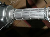 Connection wire tie-wrapped to grip, shrink-wrapped join to resistance wire just visible at right
(click on image for larger view) - Feed a length of the "grip diameter" heatshrink over the resistance wire, the grip and the connecting wire, leaving the join just proud. The heatshrink should not quite reach the raised ends of the original rubber grip. Shrink the heatshrink into place.
-
Fold the connection wire in, and wind the resistance wire spirally round the grip. You are aiming to finish the spiral 5 mm (¼ of an inch) from the other end of the grip; temporarily hold the end in place with a tiewrap. Since you won't have got the turns positioned correctly first time, gently move the spirals of resistance wire with your fingernails to even the windings.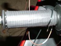 The resistance wire held temporarily with a tiewrap, the connection wire soldered, small heatshrink ready to put over the joint
click on image for larger view
- Solder another length of connection wire to the resistance wire (in my case I used two more pieces, one to each free end of my folded wire; I could have just joined them to one connection wire), heat-shrink the joint, and use a tiewrap to hold the connection wire in place, making sure the wire leaves the front of the grip with the first connection wire.
Particularly on the throttle grip, consider using some heatshrink to keep both connection wires neatly together as they emerge from the grip.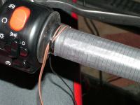 Connection wire tie-wrapped to grip, shrink-wrapped join to resistance wire just visible at right
(click on image for larger view) - Use another piece of the large heatshrink to cover the grip, the spiral, and the joins to the connection wire. Before shrinking it, make sure no wires will be visible on the outer end of the grip.
- Repeat for the other handlebar.
- Find where the switch is going to be positioned. This should be where it's unlikely to be accidentally operated, and where it won't cause a problem touching any part of the bike (or something like a tank bag) for the full movement of the handlebars. Also, the wires that will be from the back of the switch should be considered for this movement. Don't fit the switch yet, it'll be easier to connect the wires to it whilst it's free to move.
- I used heatshrink over each pair of wires to give extra mechanical protection, also making the colour a matt black, therefore less attractive to the fingers of the ungodly. Route the connection wires back to the switch. Remember, on the throttle grip, leave a loop of wire so that the throttle can be moved through its full range without any undue flexing of the wire, either where it comes out from under the heatshrink, or where it is first fixed to the handlebar or switch wiring loom or whatever.
- Note all connections to the switch terminals should be protected with heatshrink. Referring to the wiring diagram, connect two "ways" of the switch together, then connect one end of each grip to each of the switch "pole" (or "wiper") connections. The other connection wires join in with the supply wires from the frame and the in-line fuse. Be very careful to get this wiring correct, get it wrong and you could end up connecting your supply to ground. Unless you want to test your fuse, this is not very useful. I also used a piece of suitable sized heatshrink to cover the body of the switch and the wires; this acts as a general strain relief and gives some weather protection (but still expect water ingress, which is why we specified a sealed switch).
- Run the frame wire to a suitable nut or screw, preferably on the actual main frame (not the moving part), and preferrably a nut or screw that is not of structural importance (such as holding the engine to the frame). Solder the wire to a suitable sized eyelet, heatsrink over the connection, fasten the eyelet under the screw/nut.
- Position the fuse somewhere sufficiently out of sight so prying fingers won't be tempted, but where you can get at it if you need to (under the saddle?). The other side of the fuse should connect to an ignition switched circuit. I chose the one that supplies the indicators.


Testing
Visually check all your wiring. If you have an ohmmeter, you can use it to check the whole lot. Remove your fuse, measure the resistance from the feed to your switch to the frame, it should be open circuit with the switch in the "off" position. Now move the switch to one of the "on" positions, expect the meter to measure either 8 ohms or 32 ohms (or near offer), move the switch to the other "on" position, expect to read the other value. If your readings differ widely from these, you have a problem, Houston, and it needs sorting before doing anything else.
Reconnect the battery. Now put in the fuse. There should be no dramatics since the ignition is turned off. Move your grip switch to the "off" position. If you are happy with your battery's state of charge, you needn't start the engine. If you are not happy, I suggest you run the engine to keep the battery charged. In any case, turn on the ignition.
Move the switch to the 32 ohm position (if you know which this is, otherwise just turn it to one of the "on" positions). In the 32 ohm position, you can expect to feel the grips beginning to warm within 30 seconds or so. If you are in the 8 ohm position, it takes only 10 seconds. If you are in the 32 ohm position, after a minute, switch it to the 8 ohm position, you should feel the grips warming more rapidly.
When you are happy all is well, fix your switch (I tie-wrapped mine to the handlebar risers, and tiewrap the wiring to the original loom wires.
Make sure that the wires don't fret, trap, or bend excessively for any position of the handlebars or throttle.
If all is well, go ride and enjoy.
Other heat settings
As stated above, there is a big difference between the two heat settings that this simple series/parallel switching gives. There are a number of ways of changing heat settings that could be used, including:- Switching a resistor in series with the heaters
- An electronic timed on/off controller
- Using only a part of the heating wires
Switching a resistor in series
A very simple idea, however it means mounting a resistor that is going to dissipate significant amounts of heat somewhere, usually mounting the resistor on a metal plate that needs reasonable air flow. The big advantage is that, by choosing the value of the resistor, you can make the lower heat setting any proportion you like of the higher setting.
An electronic timer
The most sophisticated method that can give ideal continuous (or multi-stepped) heat settings from hottest to cold. I seriously considered this (I am an electronics engineer, and the electronics would be trivial to design). However, I was put off by- The need for a totally weatherproof construction of the electronic part
- The thought of me continually adjusting the heat setting instead of concentrating on the road ahead
Part heating
Possible worth experimenting with (when I get the time and inclination). The way my wires were laid, there are two parallel runs of heated wire on each grip, and I put in separate connection wires to these. It would be easy to alter the switching so that the "low" setting only heated one of the two wires. This would give the lower setting as half the power of the higher setting, possibly more usefull. The only possible dissadvantage I can see is the heating would be less even along the grip, and I might end up with spiral burns on my hands (see Final Warning below)!Final warning
When I first started using mine, I found two effects of note. One was that the twist grip ran slightly hotter than the fixed grip. I take that to mean some heat escapes into the handlebar, obviously more easily on the fixed side. The second effect was that, perhaps because of the novelty value of having warm hands on a cold day, I found I'd actually slightly burnt my palms and fingers after a three hour ride. Since then I've always switched to the lower setting whenever my hands begin to feel hot.
Finally ...
I sold my Trophy because arthritis in my left hand was causing difficulties using the clutch lever.On selling it to a dealer, I removed my heating elements. They had caused no damage to the original grips at all, except for very minor crushing where the tie-wraps had been. The plastic of the grips was obviously well able to cope with the temperatures involved.